How AI Handles Symbols, BOM Context and Mates in P&ID to SOLIDWORKS
A public, non-secret explanation of how AI-assisted workflows turn P&ID symbols, tags, part libraries, BOM hints and rules into reviewable native SOLIDWORKS assembly structure.

- →Layer 1: symbols and tags
- →Layer 2: BOM and part-library mapping
- →Layer 3: mates and assembly structure
- →Layer 4: validation and exceptions
- →Why model-assisted workflows are better than free-form generation
Answer block: AI helps P&ID-to-SOLIDWORKS automation by interpreting symbols, tags, connections, BOM hints and customer standards as engineering context, then proposing a native assembly structure. The system should not hide uncertainty. Ambiguous symbols, missing parts, conflicting rules and unclear mates should become review items, not silent guesses.
A P&ID is a compact engineering language. It encodes process relationships in symbols and lines, but it does not directly say where every component should sit in 3D, which SOLIDWORKS part file to use, how ports should align, or how a BOM should be structured. This is why naive “diagram to model” automation often disappoints. It treats the drawing as a picture instead of an engineering specification.
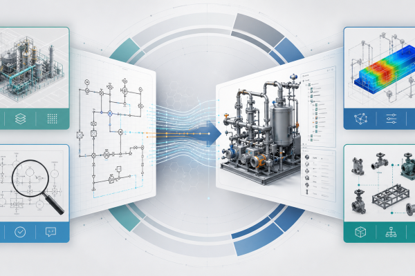
A useful AI workflow needs to bridge four layers: diagram interpretation, part-library mapping, assembly logic and validation.
Layer 1: symbols and tags
The first challenge is identifying what the diagram means. A valve symbol, instrument bubble or line break may look simple, but customer conventions vary. Tag formats also differ: one team may encode function, line number and location in a tag; another may keep that information in a separate table.
AI is useful because it can help connect visual symbols, text labels and surrounding context. The public outcome should be a structured interpretation: component class, tag, connection relationship and confidence or review status.
Layer 2: BOM and part-library mapping
The second challenge is mapping intent to real parts. A P&ID symbol is not enough to choose a physical valve or regulator. The system needs part-library data, supplier models, customer-approved components, size, rating, material and revision information.
When a part is matched, the assembly can reuse the customer’s SOLIDWORKS part files. When a part is missing, the workflow should create a placeholder or hold item with a clear exception note. This is safer than pretending the library is complete.
Layer 3: mates and assembly structure
The third challenge is turning the process relationships into a mechanical assembly. Engineers care about hierarchy: panel, stick, subassembly, purchased component, fitting, bracket and routing segment. They also care about the relationships that make revision possible.
Publicly, MST describes this as native assembly generation with feature tree and mates. The system should aim to create a structure that an engineer can open, inspect and revise. It should not be a single imported body with no design intent.
Layer 4: validation and exceptions
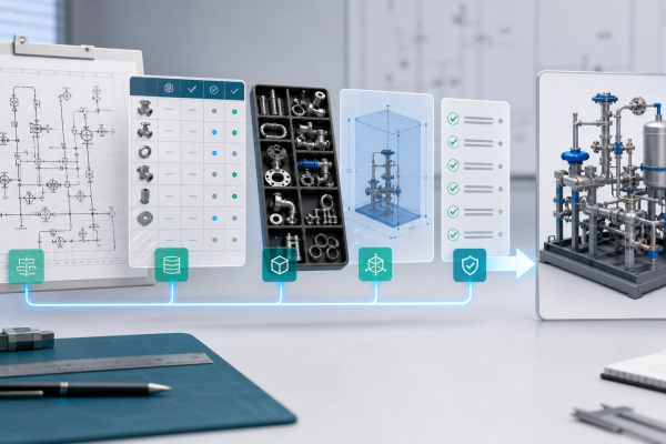
The fourth challenge is deciding what is acceptable. Rulepack validation can include naming rules, allowed components, port orientation, clearance rules, connection compatibility, required BOM fields and customer-specific standards.
AI is helpful, but it must be constrained by engineering rules. A good workflow separates three outputs:
- Generated items: confident mappings and assembly structures.
- Warnings: items that may be valid but need confirmation.
- Hold items: missing parts, ambiguous symbols or rule conflicts requiring engineer review.
Why model-assisted workflows are better than free-form generation
Free-form generation can look impressive in a demo, but industrial CAD needs traceability. Engineers need to know why a component appears, which drawing element caused it, which part-library entry was used and which rule allowed or blocked a decision.
That is why the valuable workflow is not just “AI generates CAD.” It is “AI helps structure a traceable engineering proposal that SOLIDWORKS engineers can review.”
FAQ
Does AI decide the final design?
No. AI supports interpretation and assembly proposal. The customer engineering process still owns review and release.
Can the system use our own part library?
That is the preferred path. Customer part-library reuse is what makes the output useful for real engineering work.
What happens when the P&ID is ambiguous?
The workflow should mark the ambiguity and request review. Silent guessing is not acceptable for production-oriented engineering.
Do you disclose the model architecture?
No. MST explains the workflow boundary and output expectations, not proprietary model internals.
For an intake checklist, see P&ID to Native SOLIDWORKS Assembly with Feature Tree.
Related Articles

Need a native SOLIDWORKS assembly?
Send the P&ID scope, part-library expectations, rulepack boundary and target assembly output. MST reviews whether the case is suitable for native assembly generation with feature tree, mates and BOM context.