- →What a P&ID actually encodes
- →The three stacked AI problems
- →Why "just convert the STEP" doesn't work
- →How DrawingDiff handles the hard path
- →Current status and who it's for
Key Takeaway
What a P&ID actually encodes
Open any piping and instrumentation diagram from a semiconductor gas panel, chemical plant, or fluid system. You see symbols — valves, pumps, regulators, filters, instruments — connected by lines. To a junior engineer it looks like a flowchart. To someone who has built real equipment, it’s something else:
- Implicit spatial constraints: regulators must sit upstream of sensitive actuators; bleed valves must be reachable from operator height; gas lines avoid crossing electrical paths.
- Unwritten design standards: every company has internal rules — “VCR fittings only above 99.999% purity”, “every isolation valve gets a purge port” — that aren’t in the drawing but govern the build.
- Process logic: flow direction, pressure drops, interlock dependencies that a 3D designer must respect or the system fails commissioning.
A P&ID is therefore less a blueprint and more a specification in shorthand, decoded by experienced engineers into assemblies that look nothing like the 2D layout.
The three stacked AI problems
What it is: Reading 400+ ISA 5.1 / ISO 14617 symbols from a PDF, plus company-specific variants nobody documents.
Why it’s hard: Same symbol, different vendors, different rotations, hand-annotated overrides. Generic OCR fails at 40% accuracy; engineers need ≥95%.
What it is: Deciding where every part physically goes in 3D space so pipes connect cleanly, flanges don’t collide, and operators can reach valves.
Why it’s hard: No unique solution exists. Classic 3D routing solvers produce spaghetti; AI needs to learn house-style routing from a company’s prior assemblies.
What it is: Output isn’t a STEP file — it’s a real SolidWorks assembly with features, parametric mates, and a real BOM.
Why it’s hard: STEP dumps dead geometry; native assemblies require understanding SolidWorks’ internal representation and feature tree. Every engineer can tell the difference in five seconds.
Why “just convert the STEP” doesn’t work
Most existing P&ID-to-3D tools take the easy route: generate a STEP (Standard for the Exchange of Product Model Data) file that any CAD can open. Engineers hate this for three reasons:
- No editable features: a flange diameter change means regenerating the whole file. In native SolidWorks, it’s one parameter.
- No parametric mates: moving one pipe cascades through the assembly; STEP just has fixed coordinates.
- No usable BOM: engineers spend hours re-tagging parts for purchasing. The BOM from a STEP is functionally a graveyard.
The result: “AI-generated” STEP files get opened, inspected, and deleted. Engineers rebuild from scratch. The AI provides zero value.
How DrawingDiff handles the hard path
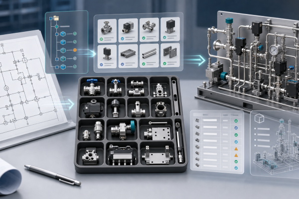
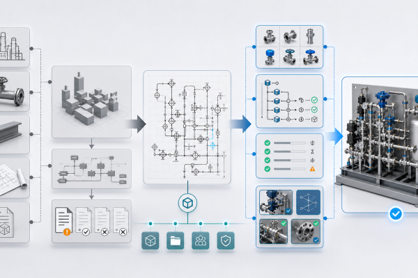
DrawingDiff takes the full native-SolidWorks route because that’s what engineers actually use:
- Symbol recognition: trained on 50,000+ real P&ID samples, fine-tuned on your company’s style sheets and internal document archives.
- Routing: learns from your existing SolidWorks assemblies — if your team always puts the filter below the regulator with a 15-cm clearance, DrawingDiff replicates that.
- Native CAD generation: outputs directly to SolidWorks feature tree, with mates, configurations, and a BOM that matches your company’s part-numbering convention.
The output is editable, refactor-able, purchase-ready. Not a dead file.
Current status and who it’s for
DrawingDiff is in early access — free for design partners. We’re working with a small cohort of equipment engineers (semiconductor gas panels, chemical process systems, fluid delivery) to refine the symbol library and routing style before general release. If you regularly do P&ID-to-3D work and want to shape the roadmap, we’d love to talk.
Try DrawingDiff with your own P&ID
Request early access — free for design partners during MVP.
Read more about DrawingDiff in MST’s Industrial AI portfolio.
Review P&ID-to-native-SOLIDWORKS assembly scope
Check whether your P&ID, BOM, part library, interface rules and spatial constraints are ready for a reviewable native assembly workflow.
Open NeuroBox D page →