答案先行
MST 将 P&ID 到原生 SOLIDWORKS 装配定位为可复核的工程流程。首轮应准备 P&ID 背景、BOM 字段、客户零件库、规则边界和目标输出,最终批准仍由合格工程复核完成。
- 在向 MST 请求伙伴确认后的下一步之前,先用本文准备一版非保密首轮 brief。
- 在 NDA 和评审路径确认前,不要把设计 IP、客户 rulepack 或受控文件放入公开表单。
- 如需确认准确范围,请通过对应 MST 页面发送简短 RFQ 或工程评审请求。
原文标题: Why STEP Files Are Not Enough: The Case for Native SolidWorks Output in AI Design Tools
- →The STEP File Illusion
- →What STEP Files Actually Contain — and What They Don't
- →The Real Cost of STEP Cleanup
- →Why "Universal" Is Not Always Better
- →What Native SolidWorks Output Means
Key Takeaway
STEP files preserve shape but discard much of the feature-tree, mate, configuration, and metadata context that production engineers depend on. For large gas-panel assemblies, cleanup can take hours because engineers must rebuild constraints, metadata, and BOM context. NeuroBox D is designed to generate editable native SolidWorks assembly proposals (.sldasm) from P&ID input and customer part libraries, reducing the STEP cleanup bottleneck through a reviewable native workflow.
The STEP File Illusion
When AI design tools first entered the mechanical engineering space, most of them converged on a common output format: STEP (Standard for the Exchange of Product Data, ISO 10303). The logic seemed sound — STEP is a universal neutral format readable by virtually every CAD platform. Ship a STEP file and the customer can open it anywhere.
Review whether your P&ID and part library can support native SOLIDWORKS assembly automation.
Choose how you'd like to connect:
But anyone who has actually tried to use a STEP file in a production workflow knows the truth: opening the file is where the problems begin, not where they end.
What STEP Files Actually Contain — and What They Don’t
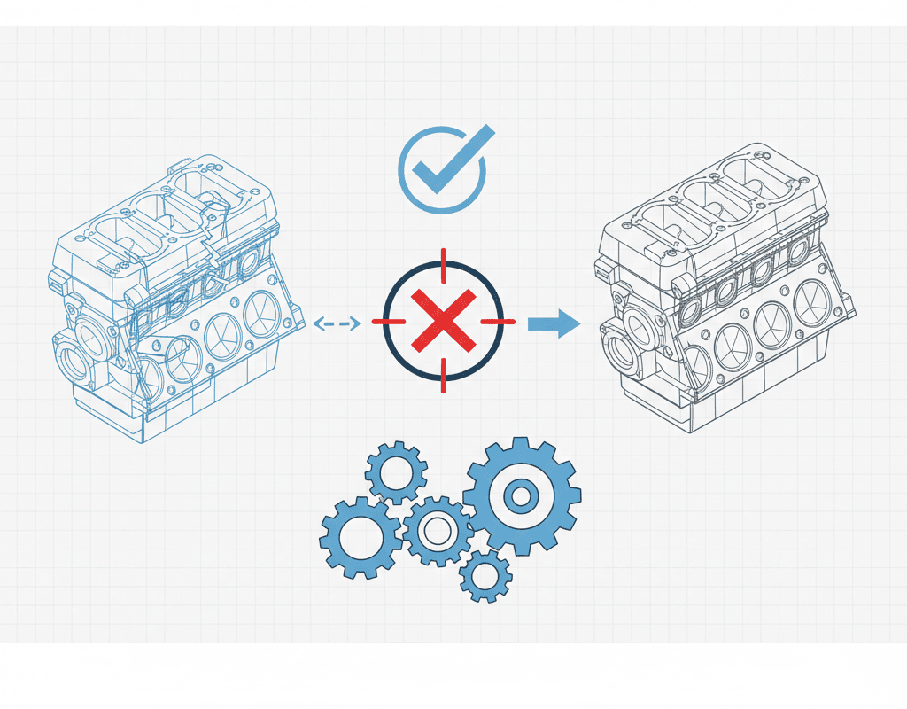
A STEP file is fundamentally a boundary representation (B-rep) of geometry. It captures surfaces, edges, and vertices with high fidelity. What it does not capture is everything that makes a CAD model useful for engineering:
- No feature tree. Every extrusion, cut, fillet, and chamfer that defined the design intent is flattened into a single “imported body.” An engineer cannot go back and modify a bore diameter or adjust a wall thickness without rebuilding the feature from scratch.
- No assembly mates. The spatial relationships between components — concentric alignments, coincident faces, distance offsets — are lost. Parts appear in the correct positions but are not constrained. Move one component and nothing follows.
- No parametric dimensions. Dimensions that drove the original design are gone. The engineer sees geometry but has no access to the design variables that control it.
- No configurations. SolidWorks configurations — variants of the same part with different dimensions or suppressed features — cannot be represented in STEP format.
- No custom properties. Part numbers, material specifications, supplier codes, and other metadata stored in SolidWorks custom properties are stripped during STEP export.
The Real Cost of STEP Cleanup
For a simple part — a bracket, a housing — the cleanup overhead of an imported STEP file is annoying but manageable. For a complex assembly like a semiconductor gas panel with 200+ components, it becomes a serious engineering burden.
Consider what an engineer must do after importing a STEP assembly of a gas delivery system:
- Identify and separate bodies. STEP imports often merge multiple parts into a single multi-body part. The engineer must manually split them and save each as an individual part file.
- Rebuild mates. Every connection between components must be manually constrained. For a gas panel with 200+ parts, this means creating hundreds of mates — concentric for tube-to-fitting connections, coincident for mounting plates, distance mates for spacing.
- Recreate features for editability. If any dimension needs to change — and in semiconductor equipment, dimensions always change — the engineer must rebuild the parametric features on top of the imported geometry.
- Re-enter metadata. Part numbers, materials, and custom properties must be manually typed into every component for the BOM to generate correctly.
- Verify integrity. After all this manual work, the assembly must be checked for interference, mate errors, and missing components.
In practice, this cleanup can take hours for a moderately complex assembly and can exceed a full working day for large gas panels, depending on component count, mating strategy, metadata requirements, and how much of the original design intent was lost during export.
Why “Universal” Is Not Always Better
The appeal of STEP lies in its universality, but universality comes at the cost of specificity. STEP was designed as a lowest-common-denominator exchange format — it represents what all CAD systems can agree on, which means it represents the minimum of what any single CAD system can do.
In the semiconductor equipment industry, SolidWorks dominates mechanical design. According to industry surveys, over 60% of equipment OEMs in Asia-Pacific use SolidWorks as their primary CAD platform. For these companies, receiving a STEP file and having to rebuild it in SolidWorks is not interoperability — it is overhead.
The situation is analogous to receiving a PDF when you needed a Word document. Yes, you can read it. No, you cannot efficiently work with it.
What Native SolidWorks Output Means
A native SolidWorks assembly (.sldasm) with its associated part files (.sldprt) preserves everything that STEP discards:
- Full feature tree: Every extrusion, cut, pattern, and fillet is intact and editable. Need to change a tube length? Edit the dimension directly.
- Assembly mates: Components are fully constrained with proper mate relationships. Move a valve block and the connected tubing follows.
- Parametric dimensions: All driving dimensions are accessible and modifiable, enabling rapid design iterations.
- Custom properties and BOM data: Part numbers, materials, supplier information, and descriptions are embedded in each component and flow directly into assembly-level BOMs and drawings.
- Configurations: Design variants can be captured as configurations within a single file, streamlining product family management.
For a production engineer receiving this output, the difference is immediate: the assembly can be reviewed in the native SolidWorks environment with feature, mate, BOM, and rule-check context preserved as far as the customer library and workflow allow.
NeuroBox D: Native Output as a Design Principle
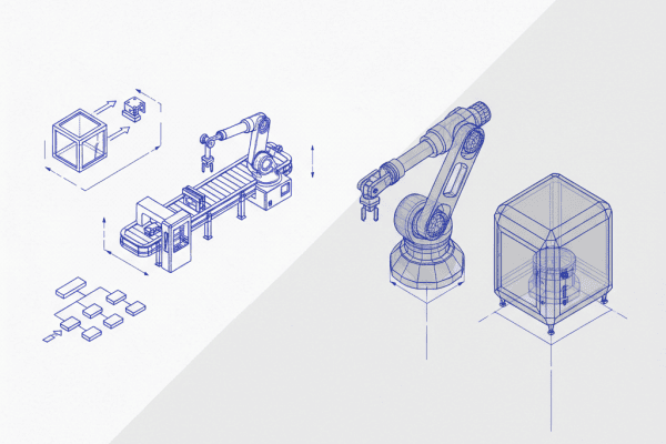
MST Singapore’s NeuroBox D was built from the ground up to output native SolidWorks assemblies — not as a format conversion afterthought, but as a core architectural decision. The AI does not generate geometry and then export it; it constructs the assembly using the same features, mates, and parametric structures that a human SolidWorks engineer would use.
This means NeuroBox D aims to produce a native, editable assembly proposal rather than a neutral-format geometry export. Engineers can open it, inspect the feature tree and mates, modify it, derive drawings, and decide what is acceptable for release under their own design-control process.
For gas panel assemblies with 200+ components, this eliminates 3–5 hours of post-processing per design — time that compounds rapidly when a team handles dozens of custom configurations per quarter.
The Standard Should Be Production-Ready
As AI design tools mature, the industry must hold them to a higher standard than “generates 3D geometry.” The relevant question is not whether the output looks correct on screen, but whether a production engineer can use it without rework.
STEP files answered the first question. Native SolidWorks output answers both.
For semiconductor equipment companies evaluating AI design platforms, the output format is not a technical detail — it is the difference between a tool that saves time and a tool that merely shifts the workload from one engineer to another.
Related Reading
Still designing assemblies manually?
NeuroBox D converts your P&ID into a complete SolidWorks assembly — in hours, not days. See how it works with your own designs.
NeuroBox covers the full lifecycle: design automation, Smart DOE commissioning, and real-time production AI.
Explore Solutions →Review a semiconductor AI workflow with MST
From Smart DOE to VM/R2R review, project impact depends on equipment data, validation scope and customer acceptance criteria.
Book a Demo →