Why AI Text-to-CAD Cannot Produce Production-Oriented SOLIDWORKS Assemblies
AI text-to-CAD can make concept geometry, but P&ID-driven equipment needs native assembly structure, mates, BOM context, part-library reuse and review exceptions.
- →Concept geometry is not an engineering assembly
- →Why P&ID is different from text-to-CAD
- →The MST position
- →FAQ
Answer block: AI text-to-CAD tools can be useful for concept geometry, but production-oriented SOLIDWORKS assembly work needs editable hierarchy, mates, BOM context, customer part-library reuse, rules and reviewable exceptions. For P&ID-driven equipment, the hard problem is not making a shape. It is turning engineering intent into a native assembly proposal that a mechanical team can inspect and revise.
AI CAD is attracting attention because it makes design feel conversational: describe a part, get a model. That is useful for ideation. It is not the same as generating a native SOLIDWORKS assembly from a P&ID for gas panels, skids, piping modules or semiconductor process equipment.
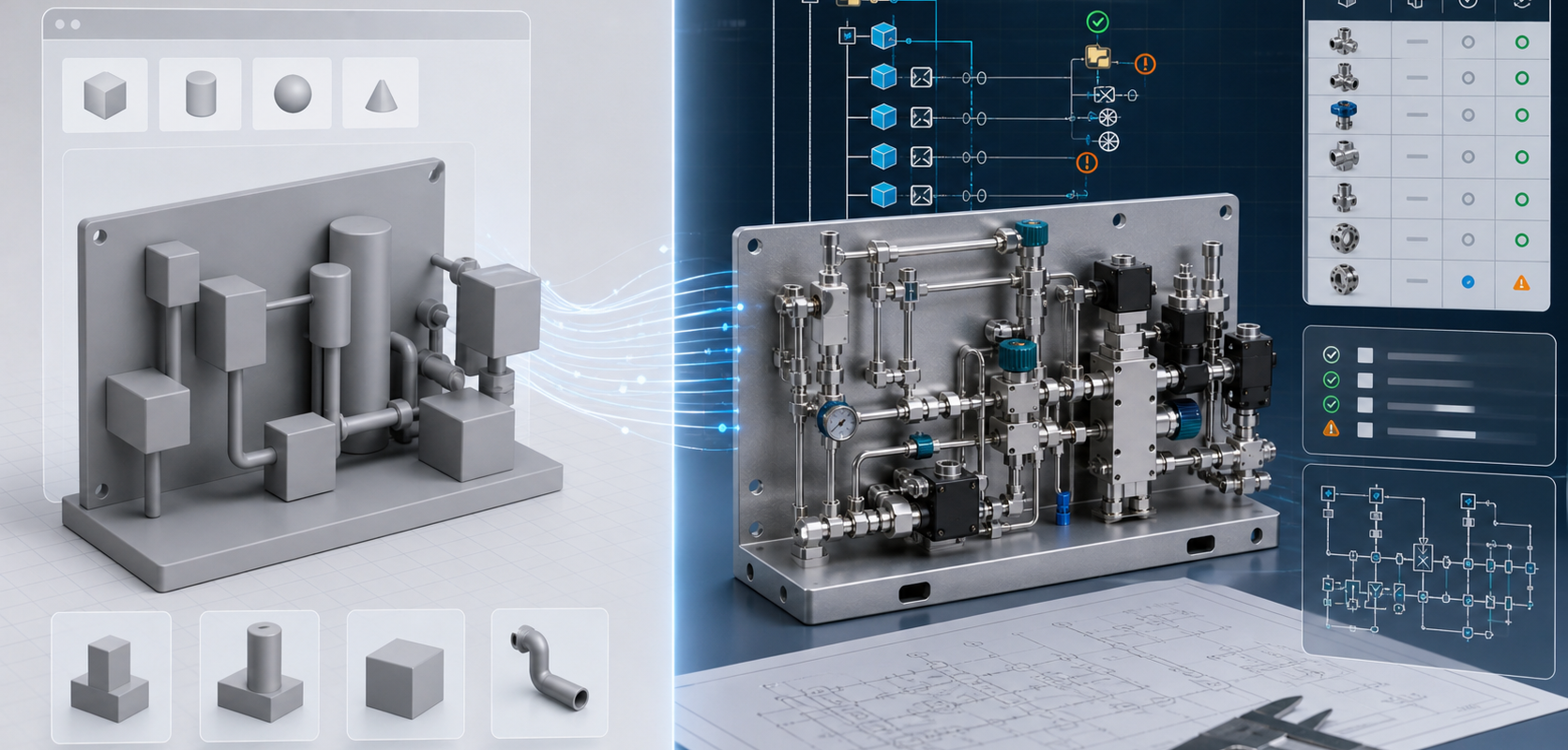
Concept geometry is not an engineering assembly
A geometry-first model may look impressive in a viewer. A production-oriented assembly has different requirements:
- Assemblies and subassemblies must be structured in a way engineers can navigate.
- Parts must map to approved components or placeholders with clear status.
- Mates and constraints must reflect assembly intent.
- BOM fields need to connect to procurement and revision control.
- Unclear symbols, tags and rules must become review exceptions, not silent guesses.
Why P&ID is different from text-to-CAD
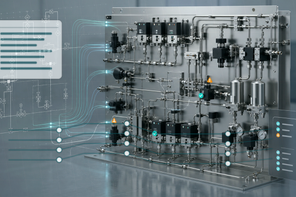
A P&ID contains process intent: valves, instruments, pumps, regulators, connections, flow direction, tags and control relationships. It usually does not contain enough physical layout detail by itself. A useful AI workflow must combine diagram interpretation with part-library mapping, customer standards, spatial constraints and engineering review.
The MST position
MST’s P&ID-to-native-SOLIDWORKS workflow is designed for a narrower and more practical target: a reviewable native assembly proposal with feature tree, mates, BOM context, customer part-library reuse and rulepack validation. The output is not a substitute for engineering release. It is a structured starting point for engineering review.
| Question | AI text-to-CAD | MST P&ID-to-SOLIDWORKS |
|---|---|---|
| Primary input | Prompt or sketch | P&ID, part library, BOM context and rules |
| Typical output | Concept geometry | Native assembly proposal |
| Engineering value | Ideation and visualization | Editable hierarchy, mates and review exceptions |
| Review role | Model cleanup | Rule, BOM and assembly validation |
FAQ
Can AI generate CAD models?
Yes, for many concept and geometry tasks. The harder question is whether the output is a native, editable assembly that fits a team’s parts, rules and review process.
Can AI replace the mechanical engineer?
No. For P&ID-driven equipment, AI should organize structure and highlight exceptions so engineers can review faster and with better context.
What makes a SOLIDWORKS assembly useful?
Feature tree structure, reusable parts, meaningful mates, BOM fields, configurations, naming discipline and clear exceptions.
Continue with Native SOLIDWORKS Assembly vs STEP Export and the MST capability page.
Related Articles

Need a native SOLIDWORKS assembly?
Send the P&ID scope, part-library expectations, rulepack boundary and target assembly output. MST reviews whether the case is suitable for native assembly generation with feature tree, mates and BOM context.