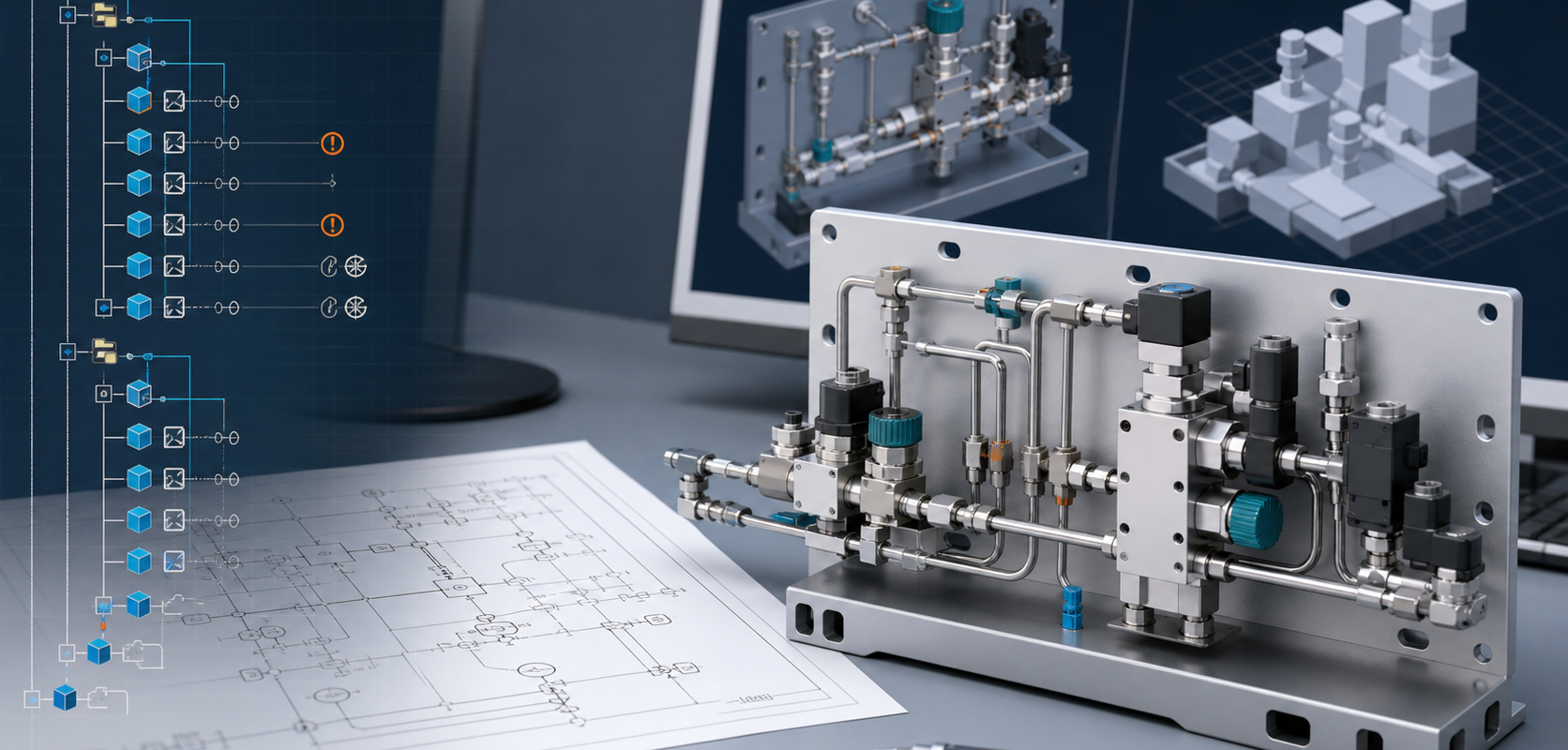
P&ID to SOLIDWORKS Assembly: Feature Tree vs STEP Export
Why native SOLIDWORKS assemblies with feature tree, mates, BOM context and reusable parts are more useful than neutral geometry export for P&ID-driven equipment design.
- →Why a native assembly matters
- →Where STEP-style output breaks down
- →What MST tries to preserve
- →How AI helps without replacing engineering judgment
- →Engineer questions
Answer block: A STEP export can be useful for geometry exchange, but it usually does not preserve the working design intent that a SOLIDWORKS engineer needs for revision, procurement and manufacturing review. A native SOLIDWORKS assembly with an organized feature tree, mates, configurations, BOM context and reusable part references is a stronger output when the goal is to keep engineering work editable after the first model is created.
For many equipment builders, the painful part is not drawing one clean 3D model. The painful part is turning a process intent, a P&ID, a part library and customer standards into a model that can survive real engineering change. A gas panel, wet bench, skid, cabinet or process module may need dozens or hundreds of valves, fittings, regulators, sensors, manifolds, tubes, brackets and purchased parts. If the output is only neutral geometry, every later change becomes a manual CAD job again.
MST’s P&ID to Native SOLIDWORKS Assembly capability is positioned for teams that need the result to remain editable inside SOLIDWORKS. The target is not a pretty viewer model. The target is a production-oriented assembly structure that an engineer can inspect, revise and connect to downstream work.
Why a native assembly matters
Native SOLIDWORKS output matters because engineering work depends on relationships, not just shapes. Engineers need to know which model is a purchased valve, which subassembly represents a gas stick, which mate controls port alignment, which configuration belongs to a customer option and which BOM item needs procurement attention.
A neutral file can show approximate geometry. A native assembly can carry structure:
- Component hierarchy for panels, sticks, subassemblies and purchased parts.
- Mates and references that make alignment and revision easier to review.
- Feature tree organization that supports engineering handoff and change control.
- BOM context so procurement is not forced to reconstruct the design from screenshots.
- Customer part-library reuse instead of generic shapes that must be replaced later.
Where STEP-style output breaks down
STEP and other neutral formats are useful, but they are often insufficient for teams that must revise the assembly. The problem is not that neutral geometry is bad. The problem is that neutral geometry is a weak handoff when the receiving team expects design intent, part identity and assembly logic.
Typical failure modes include:
- Imported parts appear as anonymous bodies, so engineers must rediscover what every component means.
- Subassembly structure is flat or inconsistent, making large modules hard to inspect.
- Part numbers, vendor attributes and procurement fields are incomplete.
- Routing intent is not visible, so a later change to port spacing or component selection becomes a manual rebuild.
- Design rules are checked outside the CAD structure instead of being visible in the engineering review flow.
What MST tries to preserve
The useful output of P&ID-to-assembly automation is not just “3D.” It is a repeatable engineering package. MST focuses the conversion around five items: recognizable components, assembly hierarchy, spatial constraints, rulepack validation and reviewable exceptions.
The system should identify what can be generated confidently, what needs a customer part-library match, and what should be held for engineer review. This boundary is important. In production engineering, a tool that silently guesses is more dangerous than a tool that marks uncertainty clearly.
How AI helps without replacing engineering judgment
AI is useful because P&ID interpretation is not a single deterministic lookup. Symbols vary by customer. Tags may be inconsistent. The same functional component can appear under different naming conventions. A real assembly also depends on part libraries, design standards, spatial envelopes and manufacturing preferences.
MST uses AI-assisted interpretation and model-guided workflow to connect diagram intent with engineering constraints. Publicly, the important point is the workflow outcome: the system can reason over symbols, tags, ports, BOM context and rule boundaries, then create a structured assembly proposal for engineering review. The internal model architecture and proprietary rule handling are not exposed.
Engineer questions
Can the assembly be released directly to manufacturing?
No. The output should be treated as a production-oriented engineering assembly that still requires customer review, rulepack validation and normal engineering release checks.
Do we need an existing SOLIDWORKS part library?
It is strongly recommended. A library allows the output to use real valves, fittings, sensors and purchased parts rather than placeholders.
Can MST handle every P&ID style?
No tool should claim that. The practical route is to review the drawing standard, symbols, tags, BOM data and target assembly standard before committing to the workflow.
What should a first request include?
Send a sample P&ID, intended equipment type, target SOLIDWORKS version, part-library status, BOM expectations, spatial boundary, rulepack notes and the review output you expect. Start with non-sensitive examples if IP review is required.
Next step
For teams evaluating P&ID-to-CAD automation, the right question is not only “Can AI make a model?” The better question is: Can it produce an assembly your engineers can trust, edit and review? Start with the P&ID to Native SOLIDWORKS Assembly capability page and use it as the intake checklist for a first review.
Need a native SOLIDWORKS assembly?
Send the P&ID scope, part-library expectations, rulepack boundary and target assembly output. MST reviews whether the case is suitable for native assembly generation with feature tree, mates and BOM context.