技术洞察
P&ID 到 SOLIDWORKS 指南:原生 SOLIDWORKS 装配、feature tree 与零件库
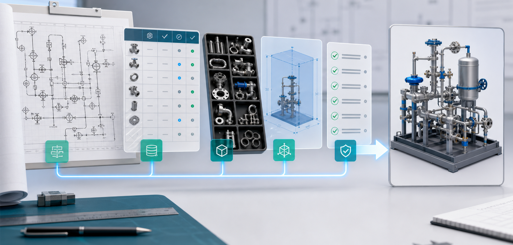
MST 将 P&ID 到原生 SOLIDWORKS 装配定位为可复核的工程流程。首轮应准备 P&ID 背景、BOM 字段、客户零件库、规则边界和目标输出,最终批准仍由合格工程复核完成。
先看结论
P&ID 到 SOLIDWORKS 指南:原生 SOLIDWORKS 装配、feature tree 与零件库
MST 将 P&ID 到原生 SOLIDWORKS 装配定位为可复核的工程流程。首轮应准备 P&ID 背景、BOM 字段、客户零件库、规则边界和目标输出,最终批准仍由合格工程复核完成。
这篇内容适合解决什么问题
- 判断 P&ID、BOM、零件库和工程规则是否足以启动原生 SOLIDWORKS 装配试点。
- 把符号、tag、阀件、接头、仪表、管路和客户标准映射成可复核的工程输入。
- 明确哪些输出只是装配提案,哪些必须由客户工程师复核批准。
试点前应准备的信息
- 代表性模块边界,例如 gas stick、gas panel、skid 或 process module。
- P&ID 样本、BOM 字段、SOLIDWORKS 版本、可复用零件库、rulepack 和验收标准。
- 连接标准、空间约束、材料要求、校验规则和最终希望生成的交付物。
公开入口不要提交什么
- 不要在公开表单上传客户保密 rulepack、未发布图纸、受控文件或完整工程包。
- 不要把输出理解为自动发布的 CAD 成品;安全、可制造性和放行仍需合格工程复核。
- 涉及客户机密或出口受控内容时,应先走 NDA 和受控文件路径。
MST 如何帮助推进
- MST 先评估输入完整度、零件库可用性、规则复杂度和可自动化边界。
- 合适项目可推进到 native assembly proposal、feature tree、mates、BOM context 和 validation notes。
- 不适合自动化的部分会在评审中标出,避免客户误以为一键生成即可生产。
Related Articles


P&ID to native assembly
Need a native SOLIDWORKS assembly?
Send the P&ID scope, part-library expectations, rulepack boundary and target assembly output. MST reviews whether the case is suitable for native assembly generation with feature tree, mates and BOM context.