- →What Exactly Is Generative Assembly Design and How Does It Differ From Traditional Generative Design?
- →How Does the AI Generate Component Placement That Follows Engineering Standards?
- →How Does AI-Generated Routing Satisfy Complex Spatial Constraints?
- →How Does the System Ensure Compliance With Company-Specific Engineering Standards?
- →What Level of Human Involvement Is Required After AI Generation?
Key Takeaway
Generative assembly design uses constraint satisfaction, learned spatial patterns, and optimization algorithms to automatically create 3D mechanical assemblies that comply with company-specific engineering standards. Unlike generic generative design that optimizes individual parts for weight or stress, this approach generates complete multi-component assemblies with proper component placement, routing, and manufacturing feasibility built in from the start.
What Exactly Is Generative Assembly Design and How Does It Differ From Traditional Generative Design?
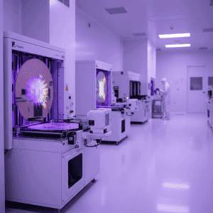
Generative design has become a buzzword in mechanical engineering, but most implementations focus on topology optimization of individual parts: given a load case and material, the software generates an organic shape that minimizes weight while meeting stress constraints. This is valuable for structural components but irrelevant for semiconductor equipment assembly design, where the challenge is not optimizing individual part shapes but arranging hundreds of standard catalog components in 3D space.
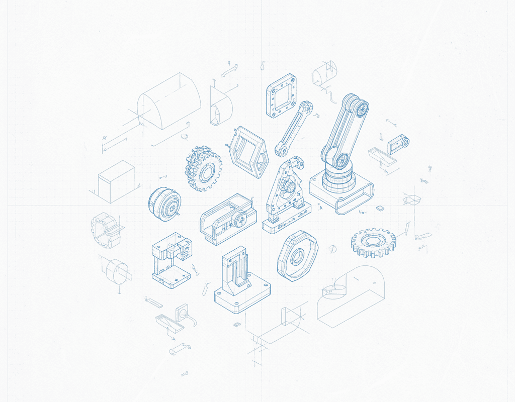
Generative assembly design is a fundamentally different problem. The inputs are not load cases and materials but a process connectivity diagram (P and ID), a component library, a physical envelope (enclosure dimensions), and a set of engineering standards (clearance rules, routing rules, accessibility requirements, safety codes). The output is a complete 3D assembly: every component positioned, every tube or pipe routed, every support bracket placed, ready for engineering review and manufacturing drawing extraction.
The distinction matters because the algorithmic approaches are entirely different. Topology optimization uses finite element analysis and gradient-based optimization. Assembly generation uses constraint satisfaction, spatial packing algorithms, graph-based routing, and machine learning models trained on historical design data. The two share the word “generative” but have almost nothing else in common technically.
How Does the AI Generate Component Placement That Follows Engineering Standards?
Component placement in a semiconductor equipment assembly is a constrained optimization problem with hundreds of variables and thousands of constraints. Consider a gas panel with 200 components in a 1,200 x 600 x 1,800mm enclosure:
Process flow constraints. Components must be arranged to follow the logical flow sequence defined in the P and ID. Gas inlet connections at the top or rear of the panel, process gas delivery at the bottom or front, exhaust connections routed to the appropriate manifold. The flow sequence imposes a partial ordering on component positions.
Accessibility constraints. Components requiring operator interaction (manual valves, calibration ports, visual indicators) must be positioned within ergonomic reach zones on the panel face. Maintenance-accessible components (filters, regulators, MFCs) must have clearance envelopes that allow removal without disturbing adjacent components.
Safety constraints. Toxic gas lines must be physically separated from non-toxic lines. Emergency shutoff valves must be accessible without reaching over other gas lines. Pressure relief devices must vent to appropriate collection manifolds. These constraints are defined by SEMI S2, NFPA 318, and customer-specific safety standards.
Manufacturing constraints. Components must be positioned to allow assembly sequence feasibility: the assembler must be able to install and connect each component without the process requiring disassembly of previously installed components. Weld joints must have sufficient clearance for orbital welding heads (typically 35-50mm radial clearance).
The AI approaches this problem through a multi-stage process. First, a coarse placement is generated using a learned spatial model that has been trained on the companys historical designs. This model captures the implicit design patterns that experienced designers follow: MFCs typically go in a specific zone of the panel, pressure regulators are grouped near the inlet, valves serving the same process line are aligned vertically. The learned model generates a placement that is architecturally sound but may contain local conflicts.
Second, a constraint satisfaction solver refines the coarse placement by resolving interference conditions, enforcing minimum clearances, and ensuring that all hard constraints (safety, code compliance) are satisfied. This solver uses techniques from operations research including mixed-integer programming and constraint propagation.
Third, a local optimization pass adjusts positions to improve soft objectives: minimizing total tubing length (which reduces cost and potential leak points), maximizing accessibility scores, and improving assembly sequence feasibility. This optimization uses gradient-free methods (simulated annealing, evolutionary algorithms) because the objective function is non-smooth and multi-modal.
The result is a component placement that an experienced designer would recognize as reasonable and standards-compliant, generated in minutes rather than the days or weeks of manual work.
How Does AI-Generated Routing Satisfy Complex Spatial Constraints?
Tubing and piping routing in semiconductor equipment is computationally challenging because it involves routing multiple paths simultaneously in a densely occupied 3D space. Each route must satisfy:
Geometric constraints: minimum bend radius (typically 4x tube OD for stainless steel tubing, 6x for specialty alloys), maximum number of bends per run (to limit pressure drop), minimum straight length before and after fittings (per fitting manufacturer specifications).
Clearance constraints: minimum tube-to-tube spacing (6-10mm typical), minimum tube-to-component clearance, minimum tube-to-enclosure wall clearance, and clearance for tube support clips at specified intervals (every 150-300mm depending on tube size and orientation).
Process constraints: gravity drainage for liquid lines, slope requirements for condensation management, dead-leg minimization for high-purity applications, and temperature-sensitive routing (keeping heat-sensitive components away from hot lines).
Manufacturing constraints: orbital weld access (35-50mm radial clearance around each weld joint), bend sequence feasibility (the tube bender must be able to form each bend without the tube colliding with the bending machine), and installation sequence (tubes must be installable without requiring previously installed tubes to be removed).
The AI routing engine uses a combination of A-star pathfinding (for finding feasible paths through 3D space) and machine learning (for predicting high-quality routing strategies based on historical designs). The space is discretized into a 3D grid, with occupied cells marked as obstacles. The pathfinding algorithm finds routes that connect required endpoints while navigating around obstacles and satisfying geometric constraints.
What distinguishes AI routing from simple pathfinding is the learned routing preferences. Trained on hundreds of past designs, the routing model learns that experienced designers prefer certain routing conventions: main gas lines run along the back wall of the enclosure, branch lines come forward to the panel face, exhaust lines are grouped on one side, and pneumatic supply lines follow consistent paths. These preferences are soft constraints that improve the quality and manufacturability of the generated routes.
How Does the System Ensure Compliance With Company-Specific Engineering Standards?
Every semiconductor equipment company has its own engineering standards, often documented in hundreds of pages of design guides, standard operating procedures, and tribal knowledge. AI assembly generation must not only follow generic engineering rules but also comply with these company-specific standards.
NeuroBox D handles this through a standards configuration layer where company-specific rules are encoded as parameterized constraints:
Component selection rules: preferred vendors by component type, approved materials by gas service, standard sizes for each application, and corporate standard part numbers that must be used when available.
Layout rules: standard panel zone definitions (which components go where), minimum and maximum component spacing by type, preferred orientations for specific component categories, and panel face layout conventions.
Routing rules: company-specific bend radius requirements (which may be more conservative than generic standards), preferred routing paths, tube support spacing requirements, and weld joint accessibility requirements that may exceed generic minimums.
Documentation rules: drawing format requirements, BOM structure and numbering conventions, dimensioning standards, and annotation requirements.
These rules are configured during the initial deployment of the AI system and are validated against the companys existing design library. The validation process checks that the encoded rules are consistent with how the company has actually designed equipment in the past, flagging any discrepancies that might indicate either an error in rule encoding or an undocumented design practice that should be explicitly captured.
What Level of Human Involvement Is Required After AI Generation?
AI-generated assemblies are not final designs. They are high-quality starting points that require human engineering review and, in most cases, some refinement. Based on data from early deployments, the typical human involvement after AI generation breaks down as follows:
Design review: 4-8 hours. The engineer reviews the generated assembly for correctness of component selection, placement logic, and routing quality. This review is faster than reviewing a manually-created design because the engineer is checking a complete assembly rather than building one incrementally.
Refinement and optimization: 8-20 hours. The engineer adjusts specific component positions, modifies routing in areas where the AI solution is functional but not optimal, and addresses any edge cases that the AI did not handle perfectly. Common refinements include adjusting instrument positions for better operator visibility, rerouting tubes in dense areas to improve assembly sequence, and modifying support bracket designs for non-standard configurations.
Documentation finalization: 4-12 hours. While the AI generates draft documentation (drawings, BOMs, cut lists), the engineer reviews and finalizes these deliverables, adding any custom annotations, special instructions, or customer-specific documentation requirements.
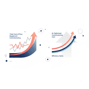
Total human involvement: 16-40 hours for a 200-component gas panel assembly. Compare this to 320-480 hours for a fully manual design. The AI handles the 80-85% of the work that is rule-governed and repetitive, freeing the engineer to focus on the 15-20% that requires genuine engineering judgment.
What Should Engineering Teams Look For When Evaluating Generative Assembly Tools?
Company-specific learning capability. The tool must be able to learn from your companys historical designs, not just apply generic rules. Ask vendors how many past designs are needed for training and how the learning process works.
Standards compliance verification. The tool should provide a compliance report showing which engineering standards each design element satisfies. This is essential for SEMI S2 certification and customer audits.
SolidWorks or CATIA native output. The generated assembly must be directly usable in your existing CAD environment, not require manual reconstruction from a visualization. Check that mate definitions, part references, and assembly structure are preserved in the CAD output.
Iterative refinement workflow. The tool should support a collaborative workflow where engineers can modify the AI-generated design and the system respects those modifications in subsequent iterations. A tool that requires starting from scratch after any manual change is impractical for real engineering work.
Routing quality metrics. Look for tools that provide quantitative metrics on the generated routing: total tube length, number of bends, minimum clearances achieved, and weld joint accessibility scores. These metrics allow objective comparison between AI-generated and manually-created designs.
Generative assembly design is moving from research prototype to production tool. For semiconductor equipment companies where 3D layout and routing consume hundreds of hours per project, the technology offers a step-change improvement in design throughput without compromising engineering quality. The companies that master this capability first will have a significant competitive advantage in design speed and cost.
Still designing assemblies manually?
NeuroBox D converts your P&ID into a complete SolidWorks assembly — in hours, not days. See how it works with your own designs.
See how NeuroBox D converts P&ID to native SolidWorks assemblies in hours, not weeks.