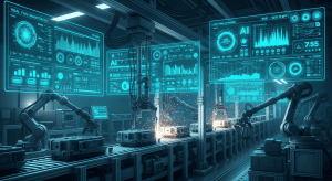
- →Why Are Gas Panels the Perfect Starting Point for AI Design Automation?
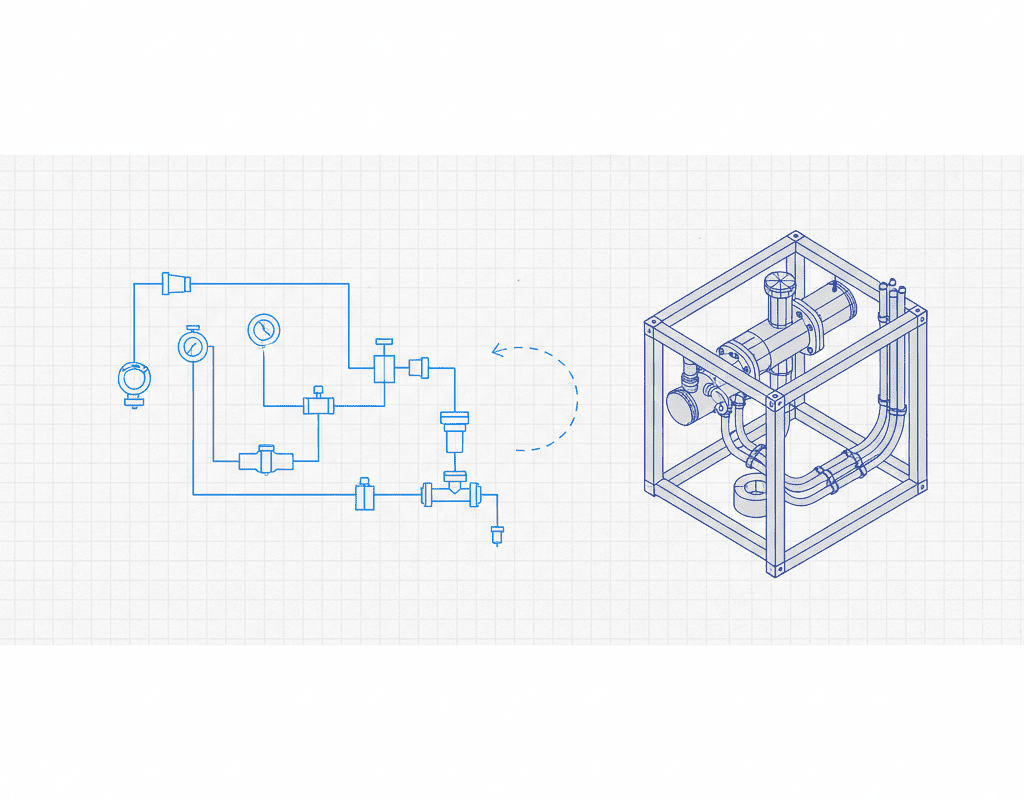
- →What Components Make Up a Typical Gas Panel and Why Do They Matter?
- →How Does NeuroBox D Handle the Specific Challenges of Gas Panel Layout?
- →What Does a Real Gas Panel Design Session Look Like With NeuroBox D?
- →What Productivity Gains Are Gas Panel Design Teams Reporting?
Key Takeaway
Gas delivery panels are the most common and most repetitive subsystem in semiconductor equipment design, with each tool requiring 2-8 gas panels containing 30-120 components each. NeuroBox D reduces gas panel design time from 5-10 days to under 4 hours by automating valve layout, regulator positioning, filter placement, and tube routing — the most frequently repeated design task in the equipment industry.
Why Are Gas Panels the Perfect Starting Point for AI Design Automation?
In semiconductor equipment manufacturing, gas delivery panels represent the highest-volume, most repetitive mechanical design task. Every etch tool, CVD chamber, diffusion furnace, and ion implanter requires one or more gas panels to deliver process gases with precise flow control, pressure regulation, and purity management.
Consider the scale. A single etch tool from a major OEM typically contains 4-8 gas delivery modules, each serving different process gases (CF4, SF6, Cl2, O2, Ar, N2, He). A CVD system may require 6-12 gas panels for precursor delivery, carrier gases, and purge lines. Across a product line of 15-20 tool variants, an equipment company designs hundreds of gas panels per year.
These panels share a common architecture — they all contain valves, regulators, filters, pressure transducers, mass flow controllers (MFCs), and tubing — yet each variant differs in component count, gas compatibility, pressure ratings, and spatial constraints. This combination of structural similarity and parametric variation makes gas panels the ideal candidate for AI-powered design automation.
NeuroBox D was initially developed and validated specifically for this use case, and gas panel design remains the platforms highest-adoption application.
What Components Make Up a Typical Gas Panel and Why Do They Matter?
A standard semiconductor gas delivery panel contains five functional subsystems, each with specific design requirements:
1. Inlet Section
The inlet section connects the gas panel to the facility gas supply. Components include manual isolation valves, inlet filters (0.003 micron for critical gases), check valves to prevent backflow, and pressure gauges. For toxic or pyrophoric gases, the inlet section also includes excess flow valves and purge connections. A typical inlet section contains 6-12 components.
2. Pressure Regulation Stage
Process gases arrive at facility pressure (typically 40-100 psig) and must be regulated down to process pressure (often 15-30 psig). This section includes single-stage or dual-stage pressure regulators, relief valves, and pressure transducers. For gases with wide pressure swing requirements, dome-loaded regulators with electronic pilot control are used. Component count: 4-8 per gas line.
3. Flow Control Section
The core of the gas panel, containing pneumatic process valves (typically diaphragm valves for high-purity applications), mass flow controllers, and the associated isolation and bypass valving. Each gas line in this section requires 5-10 components arranged in a specific sequence defined by the P&ID.
4. Mixing and Distribution
For multi-gas recipes, the panel includes a mixing manifold where individual gas lines converge. Design considerations include dead volume minimization (critical for gas switching speed), equal path length for uniform mixing, and adequate separation between incompatible gas lines. This section typically contains 8-15 components.
5. Exhaust and Safety Section
The outlet section routes mixed gas to the process chamber and provides vacuum and exhaust connections. Components include final filters, vacuum isolation valves, burst discs, and gas detection sensor ports. For toxic gas applications, the entire panel may be enclosed in a ventilated gas cabinet with leak detection — adding 10-20 additional components for the enclosure and safety systems.
In total, a mid-complexity gas panel for an etch tool contains 50-80 components, while a full gas box for a multi-chamber CVD system can exceed 200 components across 8-12 gas lines.
How Does NeuroBox D Handle the Specific Challenges of Gas Panel Layout?
Gas panel design presents several challenges that differentiate it from general mechanical assembly:
Challenge 1: Ultra-High Purity Requirements. Semiconductor process gases must maintain purity levels of 99.9999% (6N) or higher. This means every material selection, connection type, and surface finish has implications for particle generation and contamination. NeuroBox D encodes purity rules into its constraint engine — for example, ensuring that all wetted surfaces are electropolished 316L stainless steel with Ra less than 0.25 micrometers, and that connection types are appropriate for the gas service (VCR fittings for high-purity, compression for utilities).
Challenge 2: Dead Volume Minimization. The gas volume trapped between the final control valve and the process chamber directly affects gas switching speed and recipe transition time. In advanced etch processes, dead volumes of less than 5 cm3 are often required. NeuroBox Ds routing algorithm minimizes tube lengths in critical sections while respecting minimum bend radius and weld clearance requirements.
Challenge 3: Safety Spacing for Hazardous Gases. Semiconductor fabs use toxic (AsH3, PH3, BCl3), corrosive (HF, HCl, Cl2), and pyrophoric (SiH4, Si2H6) gases that require specific safety spacing between gas lines. SEMI S2 and local safety codes mandate minimum separation distances between incompatible gas services. NeuroBox D maintains a gas compatibility matrix and automatically enforces separation distances based on the specific gases assigned to each line.
Challenge 4: Service Accessibility. Gas panels require regular maintenance — valve replacement, regulator calibration, filter changes, and leak testing. Every component must be accessible for service without dismantling adjacent components. NeuroBox D applies minimum service envelope rules (typically 50-100mm clearance around serviceable components) and positions high-maintenance items at ergonomic heights (900-1500mm from floor).
Challenge 5: Orbital Weld Clearance. High-purity gas connections are made using orbital welding, which requires weld head access around each joint. Weld head clearance requirements vary by tube size — from 60mm for 1/4 inch to 120mm for 1 inch tubing. NeuroBox D automatically checks weld head accessibility for every joint and flags any violations in the design validation report.
What Does a Real Gas Panel Design Session Look Like With NeuroBox D?
Let us walk through a concrete example. An engineer at a semiconductor equipment company needs to design a 6-line gas panel for a new plasma etch tool. The gases are CF4, CHF3, O2, Ar, N2 (process), and N2 (purge).
Step 1 (0:00 – 0:05): The engineer uploads the P&ID, which the process team has provided as a PDF. NeuroBox D parses the diagram in under 30 seconds, identifying 67 components across 6 gas lines plus common exhaust.
Step 2 (0:05 – 0:10): The system presents the component matching results. 62 of 67 components are matched automatically to the companys preferred parts list. The remaining 5 are flagged for manual selection — these are custom manifold blocks that are not in the standard library. The engineer selects the correct parts from a filtered list and confirms.
Step 3 (0:10 – 0:30): NeuroBox D generates the 3D layout. The engineer specifies the panel frame dimensions (800mm x 600mm x 1800mm, a standard 19-inch rack format) and selects the mounting configuration (vertical panel mount). The AI generates three candidate layouts ranked by total tube length, accessibility score, and manufacturability score.
Step 4 (0:30 – 1:00): The engineer reviews the top-ranked layout in the 3D viewer. She notices that the CF4 pressure regulator is positioned too close to the panel edge for comfortable service access. She drags it 40mm inward — NeuroBox D automatically re-routes the connected tubes and re-validates all clearances in real time.
Step 5 (1:00 – 1:30): Tube routing is generated automatically. The system produces 89 tube segments with full bend specifications. The engineer reviews the routing in layer-by-layer view, verifying that no tubes cross in ways that would complicate installation.
Step 6 (1:30 – 2:00): NeuroBox D generates the complete output package — SolidWorks assembly, 2D drawings (12 sheets including isometric views, section details, and weld maps), BOM (67 line items), and tube cut list (89 tubes with bend data).
Total time from P&ID upload to manufacturing-ready output: 2 hours. The same design would have required 6-8 working days in the traditional manual workflow.
What Productivity Gains Are Gas Panel Design Teams Reporting?
Equipment companies that have deployed NeuroBox D for gas panel design report consistent improvements across key metrics:
- Design throughput: 4-5x increase. A team of 3 engineers that previously produced 2-3 gas panel designs per month now delivers 10-15 per month with the same headcount.
- First-pass success rate: improved from 72% to 94%. AI-enforced constraint checking catches errors that manual review misses, reducing design rework cycles from an average of 2.3 iterations to 0.8 iterations per panel.
- Material cost reduction: 8-12%. Optimized tube routing reduces total tube length by an average of 15%, and standardized component selection reduces part number proliferation by 20-30%.
- Time to market for new tool variants: reduced by 30-45 days. When design is no longer the bottleneck, new product development timelines compress significantly.
For an equipment company producing 50 gas panels per year, these improvements translate to an estimated $1.2-2.4 million in annual engineering cost savings and $5-10 million in accelerated revenue from faster time to market.
How Should Equipment Companies Get Started With AI Gas Panel Design?
The deployment path for NeuroBox D in gas panel applications follows a proven three-phase approach:
Phase 1: Library Preparation (Weeks 1-2). The companys standard parts library is imported into NeuroBox D. This includes SolidWorks part files, component specifications, and preferred vendor lists. Simultaneously, 20-50 historical gas panel designs are loaded as training data for the layout AI.
Phase 2: Pilot Design (Weeks 3-4). Engineers use NeuroBox D to redesign 3-5 existing gas panels, comparing the AI-generated results with the original human designs. This validation phase builds confidence in the system and identifies any company-specific design rules that need to be added to the constraint engine.
Phase 3: Production Deployment (Week 5+). NeuroBox D is integrated into the standard design workflow. New gas panel designs are generated by the AI and reviewed by engineers, rather than created from scratch. Each completed design feeds back into the training data, progressively improving the systems accuracy and design quality.
Gas panels are where AI design automation delivers the fastest, most measurable ROI for semiconductor equipment companies. The technology is mature, the workflow is proven, and the productivity gains are substantial. For engineering teams still designing gas panels manually, the question is straightforward: can you afford to spend 5-10 days on work that AI can complete in hours?
Still designing assemblies manually?
NeuroBox D converts your P&ID into a complete SolidWorks assembly — in hours, not days. See how it works with your own designs.
See how NeuroBox D converts P&ID to native SolidWorks assemblies in hours, not weeks.