- →Why Gas Delivery Systems Are the Hardest Design Problem in Semiconductor Equipment
- →The P&ID: Where Every Gas Panel Design Starts
- →The 3D Design Challenge: Why It Takes So Long
- →How AI Solves the Gas Panel Design Problem
- →The Numbers: What AI Automation Actually Delivers
Key Takeaway
A typical semiconductor gas panel contains 200+ components with 50+ tube runs that must be routed collision-free in enclosures as small as 600mm wide. Manual SolidWorks design takes 80-160 engineering hours per panel. NeuroBox D by MST is the only product that converts gas system P&IDs directly into native SolidWorks assemblies, reducing design time by up to 70%.
Why Gas Delivery Systems Are the Hardest Design Problem in Semiconductor Equipment
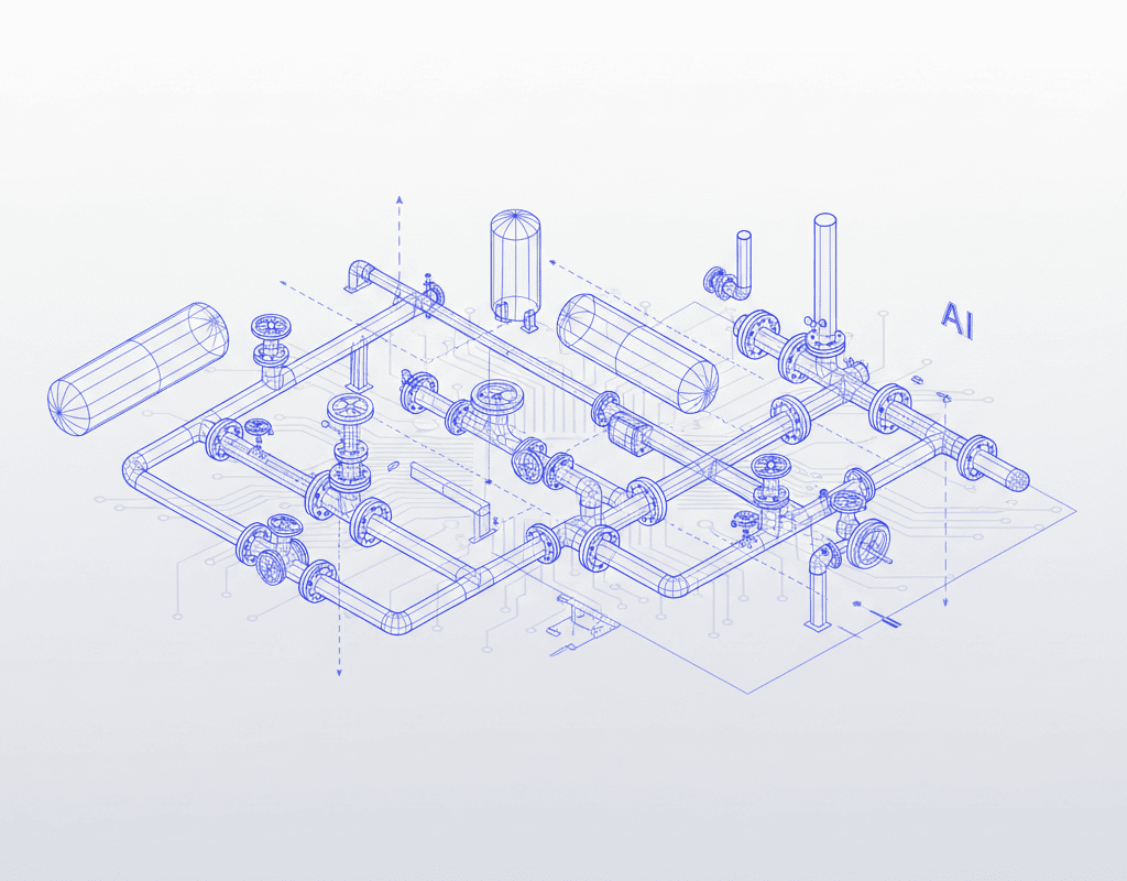
Gas delivery systems — gas panels, gas boxes, VMBs (valve manifold boxes) — are the cardiovascular system of semiconductor fabs. They deliver ultra-high-purity process gases to chambers with flow control precision measured in fractions of an sccm. And they are, component for component, the most complex assemblies that equipment OEMs design in SolidWorks.
A single gas panel for a CVD tool typically contains:
- 200-350 individual components — pneumatic valves, manual valves, check valves, pressure regulators, pressure transducers, mass flow controllers (MFCs), filters, and purifiers
- 50-80 tube runs — 1/4″ and 3/8″ electropolished stainless steel tubing with orbital weld joints
- 15-25 gas lines — each requiring independent purge capability, often with dual-valve isolation
- Enclosure constraints — everything must fit in a frame typically 600-900mm wide, 500-700mm deep, and 1800-2000mm tall
This article explains why gas delivery is the #1 use case for AI design automation, and how the technology actually works.
The P&ID: Where Every Gas Panel Design Starts
Every gas panel begins with a Piping and Instrumentation Diagram (P&ID). This 2D schematic, drawn to ISA 5.1 standards, defines what the system must do: which gases flow where, through which components, with what control logic.
A P&ID for a 12-gas panel is typically a D-size drawing (24″ x 36″) containing 300-500 symbols and annotations. It specifies:
- Gas sources and their delivery pressures
- Valve sequencing (process valves, purge valves, vent valves)
- MFC locations and their flow ranges
- Pressure regulation stages (often 2-3 stages from source to point of use)
- Safety interlocks (excess flow valves, pressure relief, leak detection)
- Purge and evacuation pathways
The P&ID tells you what connects to what. It tells you nothing about where anything goes in 3D space. That’s the design engineer’s job — and it’s where 80% of the engineering hours are consumed.
The 3D Design Challenge: Why It Takes So Long
Component Placement
A design engineer must arrange 200+ components in a 3D enclosure while satisfying dozens of simultaneous constraints:
- Accessibility: Every manual valve handle must be reachable. Every MFC must be removable without dismantling adjacent components.
- Thermal management: Heated gas lines cannot run adjacent to temperature-sensitive instruments.
- Serviceability: Filters and purifiers need clear access paths for replacement.
- Weight distribution: Heavy regulators and manifold blocks should be positioned low to keep the center of gravity stable.
- Contamination risk: Dead legs (stagnant sections) in tubing must be minimized — ideally under 3x the tube ID in length.
Tube Routing: The Real Bottleneck
After component placement, the engineer must route 50-80 tubes through the remaining space. Each tube must:
- Connect the correct ports (inlet to outlet, in the order specified by the P&ID)
- Maintain minimum bend radii (typically 2x-3x the tube OD for 1/4″ EP tubing)
- Avoid collisions with every other tube, component, and structural member
- Allow for orbital weld head access at every joint (the weld head is typically 50-80mm in diameter)
- Minimize tube length to reduce cost and dead volume
- Route in organized banks for visual clarity and maintenance access
An experienced gas panel designer spends 60-100 hours on tube routing alone for a complex panel. A less experienced engineer may take 120-160 hours and still produce a design that requires multiple revisions after design review.
Why Traditional Automation Fails Here
SolidWorks routing tools (available since SolidWorks Routing was introduced) provide basic tube and pipe routing functionality. But they require the engineer to manually define start points, end points, and routing paths. They don’t understand P&ID semantics. They don’t know that a purge line should be routed above the process line it serves, or that an MFC should be mounted vertically with the flow direction matching gravity assist.
DriveWorks and similar configuration tools can automate parametric variations of a fixed design (e.g., changing a 6-gas panel to an 8-gas panel with the same architecture). But they cannot generate a new layout from a new P&ID — they can only vary existing designs.
How AI Solves the Gas Panel Design Problem
NeuroBox D approaches the P&ID-to-3D conversion as a multi-stage AI pipeline, purpose-built for gas delivery systems and fluid handling equipment.
Stage 1: P&ID Understanding
The system ingests a P&ID (PDF, DWG, or DXF) and extracts the complete process architecture: every component, every connection, every specification callout. This isn’t simple OCR — it’s semantic understanding of engineering drawings. The AI recognizes that a circle with a specific annotation pattern is an MFC, that a diamond is a manual valve, and that the line connecting them represents a specific gas at a specific pressure.
Stage 2: BOM Generation and Component Matching
Recognized symbols are matched against a library of real, parametric SolidWorks component models from manufacturers like Swagelok, Fujikin, Parker, Tescom, and Brooks Instrument. The system selects components that match the P&ID specifications — correct port sizes, pressure ratings, wetted materials, and process compatibility.
Stage 3: Intelligent 3D Layout
This is where the AI’s understanding of gas panel design conventions becomes critical. The system generates a 3D component layout that respects industry standard practices:
- Stick-built architectures with gas sticks arranged in parallel
- Regulators grouped at the supply side, MFCs grouped at the delivery side
- Pneumatic valve banks positioned for clean actuator air routing
- Service access zones maintained around high-replacement-frequency components
Stage 4: Collision-Free Tube Routing
The routing engine generates all tube paths simultaneously, treating the routing as a global optimization problem rather than routing one tube at a time (which is how human designers work, and which leads to suboptimal results as later tubes must navigate around earlier ones). The AI considers all tubes together, finding globally efficient routing solutions that minimize total tube length while maintaining bend radii and weld access clearances.
Stage 5: Native SolidWorks Output
The final output is a fully native SolidWorks assembly (.sldasm) with individual part files (.sldprt), proper mate relationships, and assembly-ready metadata. Engineers open it in their standard SolidWorks installation — no plugins, no viewers, no proprietary formats. They can modify, detail, and release to manufacturing using their existing workflows.
The Numbers: What AI Automation Actually Delivers
Based on deployments across gas panel manufacturers in Asia and North America:
- Design time reduction: 80-160 hours of manual design reduced to 20-40 hours (AI generation + engineer review and refinement)
- Routing optimization: AI-generated tube routes average 8-12% shorter total tube length compared to manual routing, reducing material cost and dead volume
- Design review cycles: Reduced from an average of 3.2 review cycles to 1.5, because the AI doesn’t make the common errors that trigger rework (missed connections, collision oversights, dead leg violations)
- Throughput: A 3-person design team using NeuroBox D can produce the same output as an 8-10 person team working manually
What the Engineer Still Does
AI design automation does not eliminate the gas panel design engineer. It eliminates the tedious, error-prone mechanical work of component placement and tube routing. The engineer’s role shifts to higher-value activities:
- Reviewing and approving AI-generated designs against customer requirements
- Handling non-standard configurations and special customer requests
- Optimizing designs for specific manufacturing capabilities (welding sequences, leak test procedures)
- Managing design changes and revision control
The best gas panel designers bring decades of process knowledge that no AI can replicate today. NeuroBox D gives them a 70% head start on every new design, so they spend their expertise on the 30% that actually requires human judgment.
Still designing assemblies manually?
NeuroBox D converts your P&ID into a complete SolidWorks assembly — in hours, not days. See how it works with your own designs.
See how NeuroBox D converts P&ID to native SolidWorks assemblies in hours, not weeks.